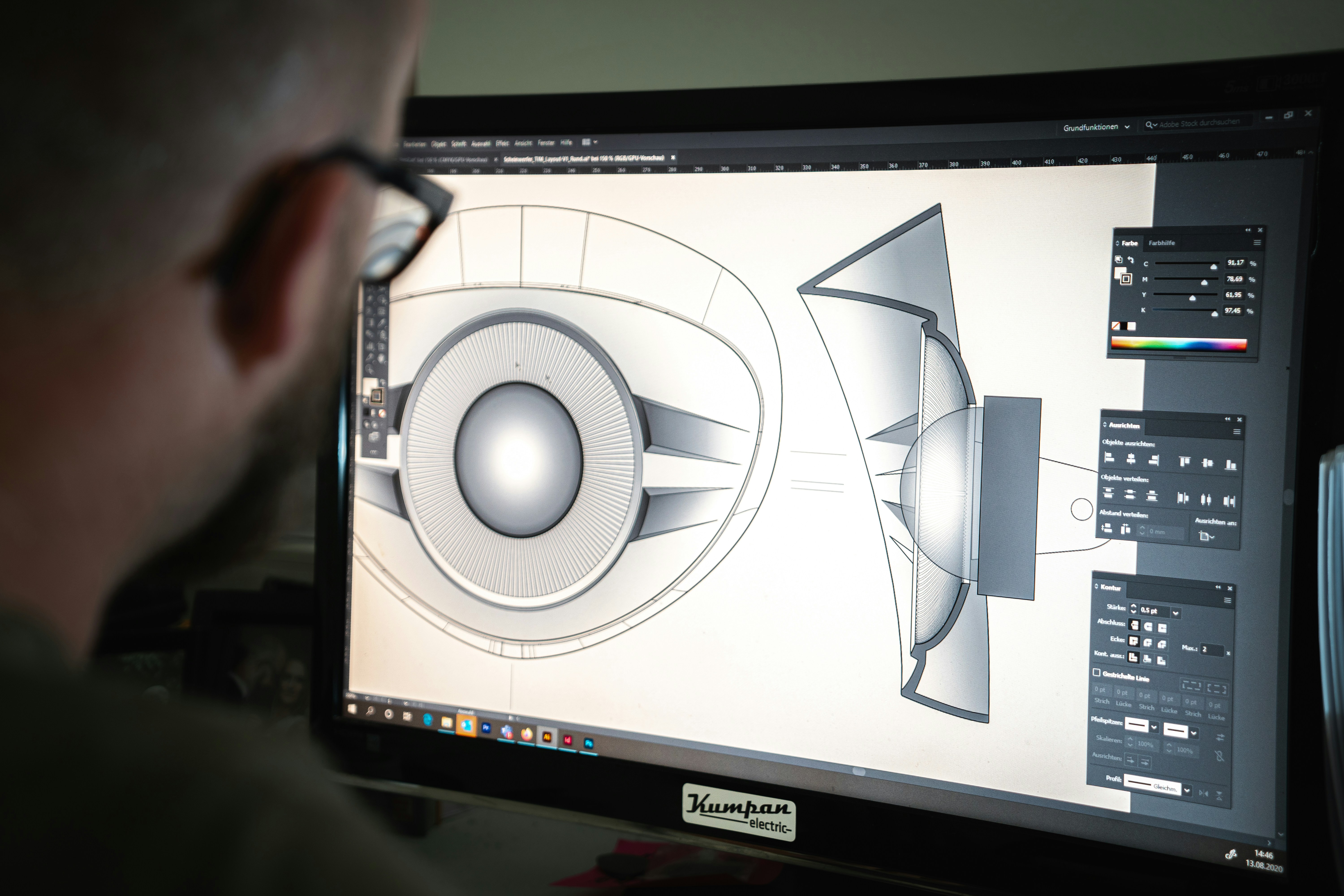
FFF, SLS, and MJF each get specified for different applications — but engineers regularly reach for whichever process they already know. A drone bracket quote goes to an FFF shop because that's what worked last time. A housing goes to an SLS vendor because someone on the team used it in a previous job. The process gets chosen by familiarity, not by requirement.
That's a problem. FFF, SLS, and MJF have meaningfully different performance profiles, material ranges, isotropy characteristics, and batch economics. Choosing the wrong one doesn't just cost money — it produces parts that fail in service, require redesign, or get rejected at incoming inspection because they don't meet the engineering spec that was never cross-referenced against the process capability.
This post covers process fundamentals, a side-by-side comparison table, a decision framework, and a concrete application walkthrough. The goal is to replace "what do I usually use?" with "what does this application actually require?"
Process Fundamentals
FFF — Fused Filament Fabrication
FFF extrudes molten thermoplastic filament through a heated nozzle, building parts layer by layer on a controlled platform. The nozzle temperature, chamber temperature, layer height, print speed, and orientation all directly determine the mechanical properties of the finished part.
The critical variable in high-performance FFF is the build environment. Standard FFF hardware runs at ambient chamber temperatures and maxes out at 260–300°C nozzle temperatures. Industrial high-temperature FFF systems may run nozzle temperatures of 420–450°C and elevated chamber temperatures depending on the polymer, geometry, and machine class. Builders Generation qualifies high-temperature polymer projects case-by-case based on material, chamber capability, annealing plan, and acceptance criteria.
Material range: The broadest of the three processes. PEEK, CF-PEEK, ULTEM 9085, ULTEM 1010, PC, PC-CF, PA-CF, PPS-CF, ABS, ASA, and specialty blends.
Mechanical properties: Anisotropic. FFF parts have a defined weak axis in the Z-direction (build direction). Z-direction tensile strength is typically 35–50% lower than XY. Representative high-temperature PEEK datasets show meaningful XY/Z strength differences, which must be accounted for in design and orientation.
Temperature capability: With PEEK and ULTEM, continuous service temperatures of 250°C and 170°C respectively. The highest thermal ceiling of the three processes for functional polymer parts.
Documentation support: Strong when the vendor controls material lot, process parameters, build orientation, inspection, and post-processing records.
SLS — Selective Laser Sintering
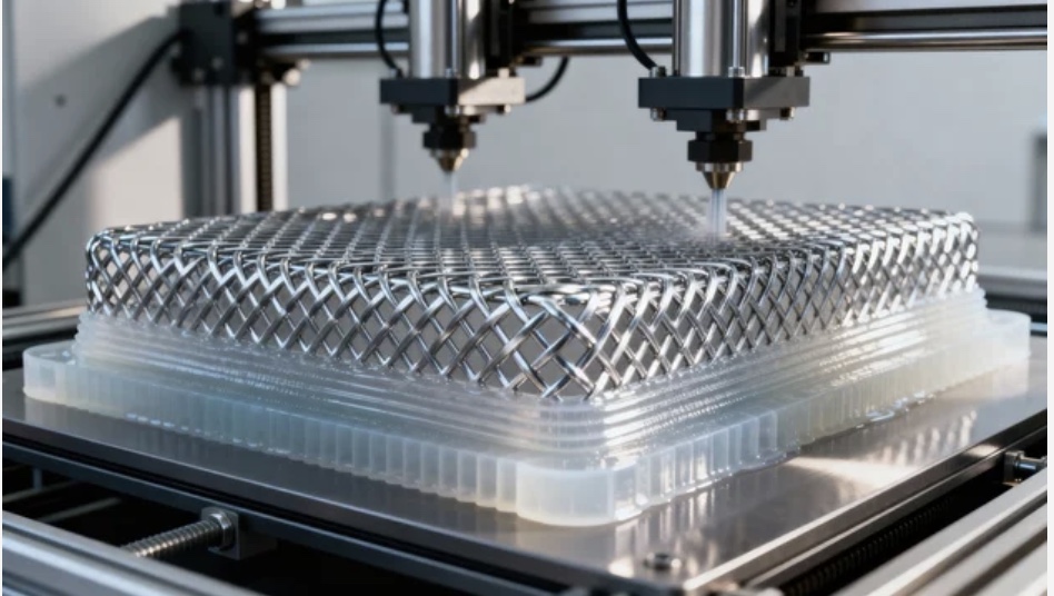
SLS uses a CO₂ laser to selectively fuse powder particles in a temperature-controlled powder bed. Each layer is spread, sintered, then a new layer of powder is deposited. The surrounding unfused powder acts as support for overhanging geometry, eliminating the need for explicit support structures.
Material range: Predominantly nylon-based. PA12 is the SLS workhorse — good mechanical properties, chemical resistance, and batch consistency. PA11, glass-filled PA12, and TPU are available on most commercial systems.
Mechanical properties: Near-isotropic. The powder bed sintering process produces parts with roughly equivalent properties in X, Y, and Z. Tensile strength variation between build directions is typically less than 10%. This is the primary mechanical differentiator versus FFF.
Surface finish: Characteristically grainy, matte texture. Ra 15–20 µm as-printed.
Batch economics: Strong. Per-part cost drops significantly at quantities of 20+ parts with 3D powder bed nesting.
MJF — Multi Jet Fusion
MJF is HP's industrial process. A printhead deposits fusing agent and detailing agent across a powder bed; an energy source fuses where the fusing agent was deposited. The detailing agent produces sharper edge resolution than SLS.
Material range: Similar to SLS. PA12 is the primary commercial material. The material portfolio is narrower than FFF's high-temperature range — PEEK and ULTEM are not available in MJF.
Mechanical properties: Near-isotropic, similar to SLS. MJF PA12 typically shows slightly higher tensile strength and better consistency than SLS PA12.
Surface finish: Better than SLS as-printed. Ra 8–12 µm on vertical walls, finer edge definition.
Batch economics: Excellent. Faster build cycles make MJF cost-effective at medium-to-large batches.
When Each Process Wins
FFF wins when:
You need a high-performance semi-crystalline polymer. PEEK, CF-PEEK, ULTEM 9085, ULTEM 1010, PPS-CF, PC-CF — these materials are either unavailable in SLS/MJF or available only in specialist configurations. If your thermal spec exceeds 150°C continuous, or your application calls for FAR 25.853 material compliance, or you need chemical resistance to Jet-A or aggressive solvents, FFF on a qualified high-temperature system is likely the only production-viable path.
Quantity is low (1–50 units). FFF per-part cost at low quantities is competitive. There is no powder cake utilization constraint — a single part runs as efficiently as ten.
You need documentation and traceability. Certificate of Conformance, locked process parameter records, dimensional inspection reports, and material lot traceability are strong with FFF when the production workflow controls the full process.
The load path can be designed around the anisotropy. FFF's Z-direction weakness is a known quantity. With proper DfAM — orienting the part so critical load paths run in XY — the anisotropy is manageable.
SLS / MJF wins when:
You need isotropic properties and can use PA12. If the mechanical requirement is for consistent properties in all axes and PA12 meets your thermal and chemical spec, SLS or MJF is the appropriate choice.
The geometry requires complex internal features. Internal channels, undercuts, and lattice structures are printed support-free in both SLS and MJF.
Batch size is medium-to-large (50–500+ parts). The economics of powder bed processes improve significantly with batch size.
Specific Stiffness: Why Material Choice Changes What Is Possible
Stiffness per unit mass — specific stiffness — is the number that governs weight-critical structural decisions. The values below are representative datasheet values and should be validated against the exact supplier, build orientation, and test standard:
# Specific stiffness comparison (flexural modulus / density)
materials = {
    "PEEK (FFF)":     {"modulus_mpa": 4100,  "density_gcc": 1.32},
    "CF-PEEK (FFF)":  {"modulus_mpa": 14000, "density_gcc": 1.44},
    "PA-CF (FFF)":    {"modulus_mpa": 7500,  "density_gcc": 1.15},
    "PA12 (SLS)":     {"modulus_mpa": 1700,  "density_gcc": 0.97},
    "PA12 (MJF)":     {"modulus_mpa": 1800,  "density_gcc": 0.97},
}

for mat, props in materials.items():
    specific_stiffness = props["modulus_mpa"] / props["density_gcc"]
    print(f"{mat:<18}  {specific_stiffness:>8.0f} MPa·cm³/g")

# PEEK (FFF)            3,106 MPa·cm³/g
# CF-PEEK (FFF)         9,722 MPa·cm³/g
# PA-CF (FFF)           6,522 MPa·cm³/g
# PA12 (SLS)            1,753 MPa·cm³/g
# PA12 (MJF)            1,856 MPa·cm³/g
The specific stiffness gap between CF-PEEK FFF and PA12 powder-bed is 5.2×. For a drone bracket or robotics arm where deflection under load is the failure mode, this is not a marginal difference — it changes what geometry is possible at a given mass budget.
Process Comparison Table
Values are representative and vary by machine, material supplier, orientation, post-processing, and test standard. Final material selection should be validated against the application load case.
| Attribute | FFF (High-Temp) | SLS | MJF |
|---|---|---|---|
| Dimensional accuracy | ±0.2–0.5 mm | ±0.3–0.5 mm | ±0.2–0.4 mm |
| Surface finish (as-printed) | Ra 10–25 µm | Ra 15–20 µm | Ra 8–12 µm |
| Material range | Broadest — PEEK, CF-PEEK, ULTEM, PC-CF, PPS-CF, PA-CF | Nylon-dominated — PA12, PA11, TPU, glass-filled | Nylon-dominated — PA12, PA11, TPU, PA12 GB |
| Isotropy | Anisotropic (Z-axis 35–50% lower) | Near-isotropic (<10% variation) | Near-isotropic (<10% variation) |
| Max service temp | 250°C (PEEK) / 170°C (ULTEM) | ~180°C (PA12 GF) | ~180°C (PA12 GF) |
| Post-processing | Support removal; anneal for PEEK | Bead blast / tumble | Bead blast; optional dyeing |
| Batch economics | Best at 1–50 units | Competitive at 20–200+ | Best at 50–500+ |
| Cert / documentation | Strong when lot, orientation, parameters, inspection, and post-processing are controlled | Moderate | Moderate |
| Typical applications | Aerospace-adjacent structures, qualification-driven brackets, high-temp enclosures | Functional prototypes, isotropic housings, complex geometry | Medium-volume PA12 production, clean cosmetic parts |
A Concrete Decision Example
Application: Drone enclosure bracket. Structural mount for a 600g EO/IR sensor payload. Operating envelope: -40°C to +120°C. Quantity: 10–50 units. Load: combined static and vibration (5–2000 Hz sweep).
Can SLS / MJF do this?
The temperature envelope is the first filter. PA12 has an HDT of approximately 175°C at 0.45 MPa — which puts it in range for 120°C survival. However, continuous service at 120°C reduces PA12 mechanical properties meaningfully. Fatigue life under vibration loading at elevated temperature for unfilled PA12 is not well characterized for flight-hardware qualification paths.
Quantity (10–50) is low for powder bed economics. SLS and MJF are not at their cost-per-part optimum here.
Verdict for SLS/MJF: Possible with PA12 GF (higher HDT), but with margin concerns at 120°C continuous, limited documentation for flight qualification, and unfavorable batch economics at this quantity.
Does FFF fit?
Material selection: PC-CF handles -40°C ductility and 135°C HDT. CF-PEEK handles the full -40 to +250°C range with margin.
Anisotropy: the bracket geometry can be oriented so the primary bending axis runs in XY. The load case is defined — orientation is a controllable design input.
Quantity: 10–50 units is the FFF optimum. Documentation: CoC, dimensional inspection, and process records are straightforward.
Verdict for FFF: CF-PEEK on a high-temperature FFF system is the better fit. Temperature capability has margin. Documentation supports qualification. Batch economics are appropriate.
Where Builders Generation Fits
Builders Generation supports high-temperature IDEX FFF programs with PEEK, CF-PEEK, ULTEM 9085, ULTEM 1010, PC-CF, and PA-CF. Projects are qualified case-by-case based on geometry, material, chamber capability, annealing plan, acceptance criteria, and documentation requirements.
Call Builders Generation when:
- The material requirement is PEEK, CF-PEEK, ULTEM, or a high-performance polymer composite
- The thermal or chemical environment is outside standard nylon capability
- Quantity is 1–100 units and documentation matters
- The application is aerospace, defense, drone, or robotics with a defined qualification path
Call an SLS or MJF shop when:
- PA12 meets your thermal, chemical, and mechanical spec
- Batch size is 50+ units and cost-per-part is the primary driver
- The geometry requires complex internal channels with no support removal access
- Isotropy is non-negotiable and the load case cannot be controlled to a single axis
The processes are not competing answers to the same question. They are different tools with different operating envelopes. The engineering requirement should determine which envelope fits — not which shop answered the phone first.
Process selection is an engineering decision, not a default. When the requirement is clear — thermal envelope, load direction, documentation standard, batch size — the right process follows. If you're working through a material or process decision for a drone, robotics, or aerospace application, bring us the spec. We'll give you a straight read on whether high-temp FFF is the right answer, and refer you out if it isn't.